Adjustable Holographic Microscope - MIT CAD Lab Research Project
CAD
Final Prototype
Summary of Research Project
The goal of this research project is to ultimately develop and deploy multiple Digital Holographic Microscopes in seaweed farms to monitor the bacteria and other organisms in the water. This would allow seaweed farmers to take protective measures when they notice certain diseases or bad bacteria in their farms’ water.
MIT published an article about the project, which dives into greater detail.
My Role & Contribution
I designed, developed, prototyped, and fabricated a fully adjustable and precisely controlled dry version of the microscope to test the technology, prove that it can be done underwater, and ultimately generate images that would be used to train our image processing algorithms.
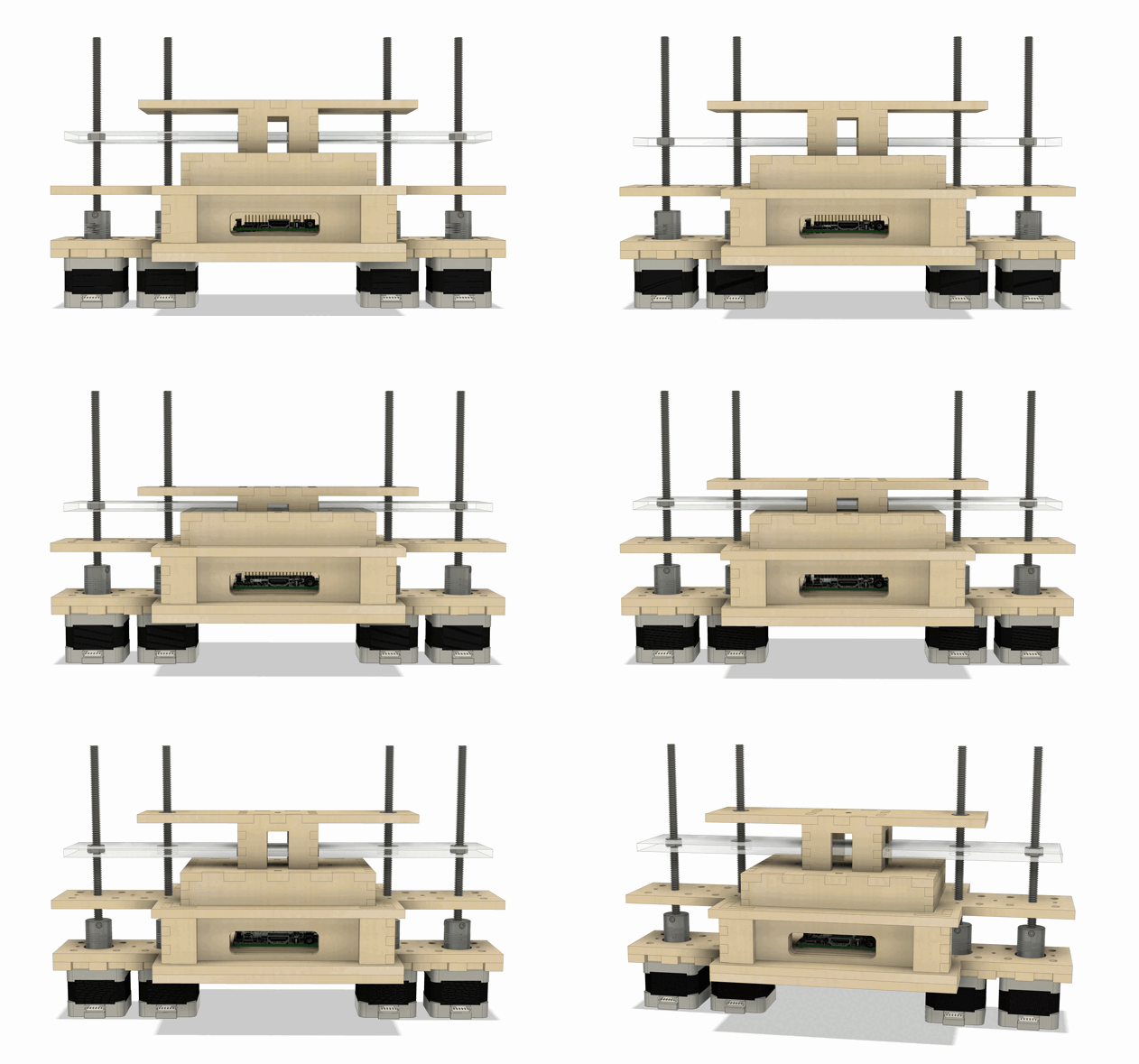
Through multiple iterations of the design (detailed below), I created a mechanism that allows a user to easily and precisely adjust the heights of two independently moving platforms.
Both the light platform and the object platform can be adjusted and moved independently of each other. This enables us to test different configurations of the platforms’ relative distances from each other, allowing us to determine which heights are optimal for producing the best images.
By using stepper motors and lead screws to control the movement of the platforms, my microscope has a theoretical accuracy of 0.00025 inches!
The Design Process
Version 1.0 - Proof of Concept
First and foremost, the concept of building a digital holographic microscope needed to be tested and proven. Using a Raspberry Pi, a camera sensor, and a laser, I designed and laser cut a set of boxes to house each of the microscope’s respective components. Using this very simple version of the microscope, we demonstrated that the technology does indeed work and I began working on a more adjustable and precise version.
CAD Model
This picture depicts what the Raspberry Pi sees. It is tinted pink because we are using a red laser as the light source, and the concentric circles displayed on the monitor represent tiny organisms or specks of dirt on the object platform. This is exactly the type of image we want to see!
Version 2.0 - Adding Adjustability
Using the same basic components as earlier, the goal of Version 2.0 was to make the microscope adjustable. By moving the object and light platforms, we would be able to determine the optimal relative distances of each platform from the camera.
By using two 1/4”-20 lead screws to adjust the heights of each platform, each platform’s positions could be changed by simply rotating their lead screws.
Version 2.5 - Stabilization Frame
To stabilize the lead screws added to version 2.0, I laser cut a stabilization frame so that all of the moving components are held steadily in place. This added some bulk to the system, but it was designed in such a way where all of the original components (Raspberry Pi box, light source, and object platform) could all be reused from earlier versions.
Version 3.0 - Adding Electronics
To control the two sets of stepper motors with an Arduino, I designed a circuitboard that connects the Arduino, four motor control boards, two sets of switches, and all additional wiring together. When I finally finished the circuit, I had a very messy breadboard that contained two switches: one switch controlled whether the object plane or the light source would move, and the other switch determined whether the selected plane would move up or down. With this working breadboard, I designed a PCB in Autodesk Eagle to replace the breadboard.
3D Model of the Stepper Motor Control Circuitboard
Original Breadboard that PCB is Designed to Replace
Stepper Motor Control Circuitboard Schematic
Stabilization Frame without Raspberry Pi and Movable Planes
Microscope Assembly Animation
To bring this microscope’s adjustability to the next level (in terms of precision, accuracy, and ease-of-use), I needed to use electronics to control the platforms’ movement. Using Nema 17 stepper motors, motor control boards, and an Arduino, I was able to write a program that rotates the lead screws incredibly precisely. Either by dialing in a specific desired height, or by manually using a button to adjust the heights of the two movable platforms, this version of the microscope enabled us to gather essential data that will constrain the design of the underwater version of the system.
With the electronics sorted out, I redesigned the stabilization frame for the microscope, this time incorporating the stepper motors into the structure.
Stabilization Frame Structure
CAD Model of the Stabilization Frame
All of the Microscope’s Individual Components
Final Product & Results
Circuitboard and Mechanism Demonstration
Final Product with Breadboard
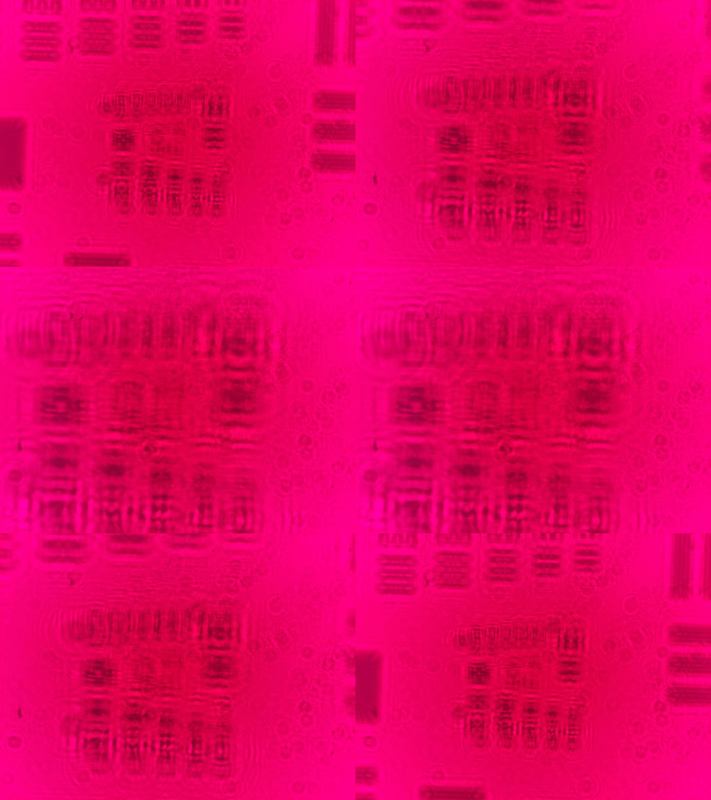
With the dry version of the microscope complete, we are able to determine the ideal parameters that generate the best image (in other words, at what heights should the camera sensor, object plane, and light plane be positioned to obtain the best photo).
These are 38 images taken by the microscope at varying heights. We are imaging a 1951 USAF Resolution Test Chart to calibrate the microscope. This animation demonstrates how even at a microscopic level, the stepper motor adjustment mechanism I designed precisely translates the planes vertically with very little horizontal movement.


